PORTABLE ALL-SKY REFLECTOR
WITH
"INVISIBLE" AXIAL CAMERA SUPPORT
(U.S. Patent No. D312,263*)
Presented at the 1987
Riverside Telescope Makers Conference
and
published in the 1988 RTMC Proceedings
by:
Jeffrey R. Charles
of
VERSACORP
http://www.versacorp.com
jcharles@versacorp.com
This is an updated version of the paper which includes color images.
© Copyright 1987, 1988, 1996, 1997 by Jeffrey R. Charles, All Rights Reserved.
Necessity is the mother of invention, and it often provides the motivation to use everyday items for bizarre functions they were never intended to perform... and the means used by myself and many others to obtain all-sky photos are no exception!
Finding an affordable way to photograph the panoramic terrestrial scenery in Rocky Mountain National Park provided the incentive for designing and building my first (and my most unusual) all-sky reflector in 1977 to obtain an UNINTERRUPTED picture of the entire horizon. This early design was the basis for the all-sky hubcap reflector featured in this article.
There are two projections which permit the entire horizon to be recorded. One is a straight 360 degree panorama, taken in separate shots or in one spin of a panoramic camera. This projection provides a pleasing picture of terrestrial subjects but does not work well when the entire sky is the subject of interest.
The second projection records the horizon as a circle, with straight up (the zenith) or straight down in the center of the picture. As with a straight panorama, separate pictures can be spliced together... but only if they are each printed on a specially made curved and tilted easel! (I did this once, and it took over 100 hours of design and darkroom work! - This was well before programs like Photoshop were available, or even P.C's for that matter!). Enter a more elegant solution: Any lens or convex reflector having more than 180 degrees coverage will accomplish the same thing (i.e. photograph the entire horizon) in one exposure when pointed straight up or down. At the time, I had a reflector from a burned out projector bulb which would cover about 240 degrees. Its image quality was poor, but it would do as a temporary solution.
The only lenses which significantly exceed 180 degrees coverage are the 6 mm f/2.8 and 6 mm f/5.6 Fisheye Nikkors, which cover 220 degrees. Since I could not afford either of these and really wanted more like a 260 degree angle of view, I began looking for suitable reflectors. To minimize radial compression of the subject toward the edge of the field (as occurs with fisheye lenses and spherical reflectors) a prolate ellipsoidal, parabolic or hyperbolic reflector is required. Such a reflector will cause the image scale to increase toward the edge of the field, but fortunately, this will not result in reduced illumination at the edge of the field as would occur with a refracting system. The Spiratone Birds Eye attachment uses a parabolic reflector, but it only covers 210 degrees, so the search continued.
Inspired by the quality of a reflected image in the side of an old General Mills toaster, I tried numerous metalized reflectors, from pots and pans to hubcaps to Christmas ornaments, and finally stumbled onto the chromed L'eggs hose egg. It's parabolic! "Sheer" luck I guess. While enduring the stares of other shoppers at local grocery stores, I searched in vain through the L'eggs displays for some Sheer Energy eggs without scratches on them. When some ladies at work heard of my plight, they gladly donated a dozen empty chrome eggs to my cause; laid 'em right on my desk. A few of them were scratch free, and since they were empty, I didn't even have to figure out how to get rid of the contents!
Axial Strut Wide Angle Reflectors can be made from simple materials.
All text and images
© Copyright 1977, 1986, 1987, 1988, 1996, 1997, Jeffrey R. Charles, All Rights Reserved.
 |
 |
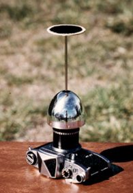
| 320 degree wide angle reflector which I built in 1977. It uses a L'eggs hose egg for the reflector. The camera lens is behind the small hole in the center of the reflector. The flat mirror at the top of the axial support strut allows the camera to "see" a reflection of the L'eggs reflector. I patented a version of this design which uses a better reflector. (U.S. patent No. D312,263). |
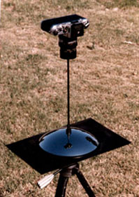
All sky reflector with axial camera support which I built in 1985. The reflector is a common hubcap. The angle of view is about 190 degrees. Other reflectors can offer a greater angular coverage. Because the reflector is large, this system can be used at f/ratios as fast as f/2. An improvement of this version is also covered in my patent. |
All text and images
© Copyright 1977, 1986, 1987, 1988, 1996, 1997, Jeffrey R. Charles, All Rights Reserved.
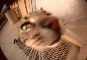 |
| Even ordinary subjects can appear unusual when photographed with an extremely wide angle lens. This is my cat, Moses. |
Return to Beginning of Article
I wanted the sky to be centered in the picture, so the reflector had to point up, but since I wanted to see through the camera finder while taking the picture, the camera had to be under (i.e. behind) the reflector. The solution was to use a "Cassegrain" design (see photo). A 75 mm F.L. enlarging lens is used to photograph the virtual image formed by the reflector. Since this design uses two reflections, it has the added advantage of producing an unreversed image.
To prevent interruption of the horizon, the flat secondary mirror was held in place by an extendible axial support rod made from part of a telescoping radio antenna. The antenna is supported in front of the 75 mm taking lens by a piece of Plexiglass having a hole drilled in its center. A hole in the center of the L'eggs wide angle reflector permits the taking lens to "see" the secondary mirror. Since the axial support rod is coincident with the reflection of the hole in the center of the wide angle reflector, it's invisible in the picture!
The axial support rod is superior to a glass enclosure as used on the Spiratone Birds Eye attachment because of its lower cost and virtual freedom of unwanted reflections. Built at very low cost using simple tools, this compact "Omnilens" has an unprecedented 320 degree angle of view! The effective focal length of the L'eggs "lens" is 4 mm, with a useful aperture range of from f/6.5 to f/11. The "blind" area directly in front of the reflector which is not included in the picture is about 60 degrees in diameter, which is not a problem for terrestrial photography. If larger reflectors are used, this figure can be reduced to as little as 15 degrees and the f/ ratio can be faster. This is because the useful aperture of the taking lens is limited by the size of the hole in the wide angle reflector. A further refinement would be to use a curved secondary mirror to help flatten the virtual image and further reduce distortion.
Return to Beginning of Article
When photographing the entire night sky instead of terrestrial subjects, different factors need to be emphasized when selecting a wide angle reflector. Since only the sky is your subject, it is not necessary to exceed 180 degrees coverage, but high resolution, a fast focal ratio, and minimal obstruction are a must. If one cannot afford a good, fast, fisheye lens, the wide angle reflector is the best choice. The reflector can be spherical (though a parabolic one would still be preferred) because the radial image compression of a spherical reflector is not too serious for an angular coverage of 180 degrees or less.
To cover 180 degrees, a convex reflector need only be an 80 degree section of a sphere, rather than the 90 degrees you might expect. This is because the angle from a "normal" camera lens to the edge of the reflector is inclined about 10 degrees from the optical axis. To estimate if a reflector has enough coverage, hold it over your head and look at it from about twice its own diameter. If you can see the whole horizon (or the walls of the store you are in) around the edge of the reflector at once, the reflector has enough coverage.
For high resolution and contrast, the reflector should have a smooth, consistent, and highly reflective surface (second surface reflectors are generally not acceptable because they are likely to produce double images). To check for irregularities, slowly rotate the reflector while looking at the reflection of a straight line or elongated light source (such as a fluorescent light) in it. If the reflection does not stay sharp, or if it seems to shimmer, widen in places, or look squiggly, the reflector is not smooth enough. Simply looking to see if a stationary reflection looks sharp is not an adequate test. Your camera will be "seeing" a virtual image of the sky which is effectively located behind the reflector, rather than being focused on the reflector itself. Since the maximum aperture of your camera lens is much larger than the pupil of your eye, more of the reflector will be used to image each point of your subject than you can use at once with your eye.
The reflector should be fairly large; at least 15 cm in diameter. This is because the virtual image from the reflector is slightly curved (in the same direction as the reflector, but not as sharply). Since the depth of field of a lens is shallow at close distances, the camera lens would have to be stopped down to sharply focus the entire virtual image from a small reflector. The effective f/ ratio of an all-sky reflector system is about the same as that of the taking lens, and you don't want the system to be much slower than f:2.8. So much for the 7 cm diameter L'eggs egg and the even smaller reflector of the Spiratone Birds Eye attachment! The surface quality on the new eggs isn't very good anyway.
From previous and current experimentation by others and myself with various reflectors, I determined that a large aluminized glass condenser lenses produce the sharpest results, IF they are big enough. However, obtaining a large lens and having it aluminized can be quite expensive. Dome shaped shiny metal kitchenware or hubcaps are a more practical solution for my applications and budget. Other astrophotographers have been successfully using "Moon" hubcaps as all-sky reflectors for years. They're widely available, inexpensive, lightweight, and have a large diameter. Some parabolic ones are even available. The large diameter of a hubcap helps offset the effects of its poorer surface quality as well as permitting photography at focal ratios as fast as f/2! With all of these advantages, I decided to give the hubcap a spin. While returning to Phoenix from the 1985 Texas Star Party, a couple of other astrophotographers and I found some 9" spherical hubcaps at a truck stop in Tucson, AZ. After searching through the whole bin full, we found one exceptionally good hubcap each.
Except for those taken with fisheye lenses, every all-sky picture I'd seen had some sort of 3 strut camera support interrupting the sky. Using a single arm camera support strut similar to that on a photo copy stand seemed an obvious and significant improvement, but even a single strut would be distracting in an all-sky picture. One strut is better than 3, but none is better than one, so I decided to use the axial support rod principle from my earlier L'eggs design to hold up the camera. The end result is very portable and only weighs 0.8 kg! It can be used for hand held landscape pictures by day, and piggyback mounted all-sky shots by night. No support struts are visible in the picture; just a small, dark, "camera nebula" in the center! (see photos at end of article).
Return to Beginning of Article
Whenever a picture is obtained by shooting STRAIGHT into a reflector, it is obvious that the camera TAKING the picture will also be visible IN the center of the picture. The closer a camera is to a given reflector, the larger it will appear in the picture. For stability, it is best if the camera is not much more than 2 reflector diameters away from a hubcap-sized reflector. This means that a 35 mm camera will be a significant size in the picture; a minimum of about 10 x 16 degrees, or almost 10% of the angular "diameter" of the sky. This is the result you will get if you use a normal 50 mm camera lens. I personally use a 35 mm wide angle lens, so the camera has to be closer to the reflector in order to get a good image size; therefore, the reflection of the camera in my reflector is more like 13% of the angular "diameter" of the sky.
Since the reflection of the camera is in the center of the picture, the image of any axial camera support structure will be coincident with the image of the camera, and so will not be visible in the picture, provided said structure is small enough that the image of it is not larger than the image of the camera. Since the focus of your camera lens will be set at a distance beyond the end of the axial strut, it can be seen that the end of the strut farthest from your camera will be in the best focus. At this distance, the support strut's diameter can be close to that of the apparent size of the shortest dimension of the reflection of your camera in the reflector (about 12 mm if you are using a 50 mm lens, somewhat larger if you are using a wide angle lens).
Closer to the camera, the maximum allowable diameter of the strut becomes smaller. The most critical area is the end of the strut closest to the camera lens (i.e. the top) which will be far out of focus. Here the strut diameter must be small enough that the bulk of its defocused image (which is much larger than a sharply focused image would be) is hidden inside the camera reflection. If it is slightly too large, it will cause a gradual, but excessive, darkening of the picture toward the center. If it is far too large, it will appear as a fuzzy edged black spot in the center of your picture. Because of this, you can see that you would not want to stop your camera lens down too far! The following table gives the maximum allowable diameter for the top end of the strut with lenses of various focal lengths and f: ratios. Unless it is conical, the top 30% or more of the strut should be the diameter shown in the table. For added stability, you can increase the diameter of the strut below this point.
Return to Beginning of Article
The following will assume that many readers only have access to simple tools, and that the hubcap reflector used is an 80 degree to 90 degree segment of a sphere, with a diameter between 22 and 26 cm.
Table 1
Lens to Reflector Distance &
Maximum Diameter for Top End of Strut
Lens		Focal Ratio:		Distance from 	Lens
Focal	1.4*	2.0	2.8	4.0	Front of Lens 	Focus
Length	Max. Diameter for Top of strut:	to Reflector	Setting

28 mm	5.5	5.5	4.8	4.0 mm	25 cm		40 cm
35 mm	7.1	7.1	5.5	4.0 mm	31 cm		51 cm
50 mm	8.7	8.0	6.5	4.8 mm	45 cm		70 cm
55 mm	9.5	8.7	7.1	4.8 mm	49 cm		76 cm
80 mm**	- -	10.0	8.7	7.1 mm	44 cm		69 cm
* f:1.4 may not provide enough depth of field for the curved virtual image.
** 80 mm lens specifications are for 4.5 x 6 cm film format.
If the end of the axial strut is within an inch or so of the front of your camera lens, it will cause a slight darkening of the picture toward the center. The diameters given in the table will limit this darkening (or "anti-vignetting") to a reasonable maximum of 25%, or 1/2 stop. This can be reduced further by making the top end of the strut smaller, or more importantly, by terminating the strut farther from the front of your camera lens. This can be done by making an extended cell or bracket which will position the Plexiglass window (in which the end of the strut is fastened) farther from your camera lens. Remember that the Plexiglass window will need to be larger if it is farther from your camera.
From the foregoing description, it can be seen that in order for the axial strut to be "invisible", it must be of sufficiently small diameter. Its maximum diameter at any given point is roughly described as a quasi-conical shape having a top diameter equal to the size shown in the table, and having a bottom diameter slightly smaller than the apparent size of the short dimension of the reflection of your camera in the reflector. It is not necessary to "fill up" all of this available space to achieve adequate stability. Knowing this, you can improvise accordingly. The strut I use adequately supports the camera, even though it only has a 6 mm diameter for its entire length.
Because of its stiffness, a piece of unthreaded steel rod (preferably drill rod) is a good choice for the top part of the strut. A piece of 1/2" - 13 threaded rod can be used for the lower part of the strut and will provide a good way to tie everything together. This piece should be at least 12 mm longer than the height of your reflector. For attaching the reflector to a tripod or piggyback mount, drill and tap a 1/4" - 20 threaded hole in one end of the threaded rod. For a base, use a 4 cm (1.5") or larger heavy plastic pipe end cap. Drill a hole in the center of the cap for the threaded rod, then attach it to the threaded rod by screwing a nut on from each side (see drawing). If you use a reducing adapter instead of the end cap, you can clean up the threads with a large tap, then screw it on to the threaded rod. To secure it, screw one nut down against it from the top. Some people may prefer a large plywood base to either of the above.
In the top end of the threaded rod, drill a hole 4 cm or more deep to accept the drill rod. If there is enough thickness in the side of the threaded rod, you can drill and tap a hole for a set screw to further secure the drill rod. Still another option is to use a smaller diameter threaded rod instead of the drill rod for the top of the strut. Even though this will be somewhat less stable, it will allow you to screw both strut sections together. In making these suggestions, it is assumed that you will want to disassemble your all-sky reflector for transportation.
Like the base, the hubcap will need to have a hole in its center for mounting it to the threaded rod. When drilling this hole, care must be taken not to bend the hubcap with too much drilling pressure. A rounded piece of soft wood under the center of the hubcap can prevent bending while you are drilling. As with the base, you can mount the hubcap on the threaded rod between 2 nuts. If you are using a 50 mm lens, the top nut will appear larger in your picture than the short dimension of the reflection of your camera. In this case, you may want to leave the top nut off and mount a large fender washer on the threaded rod under the hubcap to prevent tilting. A wood base which is larger than the hubcap will also prevent tilting.
Use a piece of 20 mm or 25 mm (3/4" or 1") thick Plexiglass for an optical window. Leave the protective paper covering on the Plexiglass during the following steps. Drill an accurately perpendicular hole 15 mm (5/8") deep in the Plexiglass for the drill rod. This hole should be positioned so that it will be accurately centered (within .1/2 mm or 020") in front of your camera lens when you use your completed reflector. Glue the drill rod into the window when it is completed.
A couple of easily constructed fixtures can be used to attach the camera to the Plexiglass window. One is to make a square or "D" shaped window about 7 cm square and attach a camera mounting bracket to the flat side. The bracket should have a 1/4" - 20 screw for the camera tripod socket. This design provides good support for heavy cameras and makes it easy to position the camera a couple of inches away from the end of the Plexiglass window (and thus the end of the strut) to minimize the "anti-vignetting" effect of the strut.
Another method is to use a round window which is enclosed in a machined cell or attached to a filter step-up ring (see drawing). The male threads of the ring should fit the filter threads on your camera lens. The female threads should be for a larger filter size. This design is more compact, easier to attach to the camera in the dark, and provides automatic centering and squaring on of the camera. The Plexiglass window should be made so it will fit tightly into the step-up ring, then be glued in. If you are using simple tools, it may be easier to make the window with 3 small evenly spaced humps around its circumference which will fit tightly into the ring, rather than trying to make the window perfectly round.
When using your reflector, place a sheet of black cardboard or other dark material behind the hubcap to eliminate any distracting background outside your all-sky circle. All-sky photography is fun and useful. Try it during meteor showers or a total Solar eclipse! If your reflector covers more than 180 degrees, or if you use the reflector sideways, you can take ultra-wide angle pictures of terrestrial scenery. Reflect on that!
Return to Beginning of Article
Return to Versacorp Home Page / Articles & Papers
Return to Versacorp Home Page
© Copyright 1977, 1986, 1987, 1988, 1996, 1997 Jeffrey R. Charles.
All Rights Reserved.
The following referenced illustrations are not posted. When posted, illustrations are expected to total ~400 k. Captions for some future photos are shown below:
Photo of wide angle reflectors, lenses, & gadgets: A few of the wide variety of devices which can be used for all-sky photography. Left to right starting with front row; Nikon 16mm fisheye lens, Soligor 180 fisheye attachment, 180 "door peeper", Spiratone Birds Eye attachment (which uses an aluminized aspheric condenser lens), Christmas ornament, "Moon" hubcap, L'eggs Sheer Energy hose egg. Back row; surplus wide angle objective, home made scanning slit camera (shown partially completed) which will photograph an area covering ~110 in declination (centered on the celestial equator) and even more in R.A., metal pan lid. Of these, only the fisheye lens, hubcap, surplus lens, scanning camera, and the pan lid can be used at fast enough focal ratios to be practical for astrophotography.
Photo of axial strut all-sky hubcap reflector: Axial strut all-sky hubcap reflector shown on tripod with camera attached. Black cardboard eliminates distracting background around hubcap. All photos in this article are by the author.
Photo of wide angle reflector made from L'eggs egg: "Cassegrain" axial strut all-sky reflector using chromed plastic L'eggs container. If larger reflectors are used, this design can also be used for all-sky astrophotography.
All-sky photo of summer Milky Way: All-sky photo of summer Milky Way from south of Phoenix, AZ. 6 minutes @ f:2 on Konica 1600 film. Note that the single axial camera support strut is invisible in the picture!
Unusual 320 degree photo taken inside the tube of a Newtonian telescope: Pierre-Y Schwaar looks quizzically at the chrome egg used to take this picture inside his 20" Newtonian telescope.
Photo of Plexiglass window at end of axial camera support strut: Detail of Plexiglass window and its cell with end of axial support rod in center. Threads on cell fit filter threads on camera lens.
Photo showing disassembled axial strut all-sky hubcap reflector: All-sky reflector can be disassembled without tools in seconds for easy transportation.
All-sky photo showing thunderstorm, fireworks display, and people on couch looking at fireworks: Fireworks and thunderstorm on July 4 from Estes Park, Colorado.
Horizontal wide-angle photo of Jack Eastman observing: Jack Eastman observes Mars through his Clark Refractor at the 1986 RTMC.
Return to Beginning of Article
Return to Versacorp Home Page / Articles & Papers
Return to Versacorp Home Page
Commercial Wide Angle Optics and related technology available for licensing:
Versacorp Axial Strut Reflectors, Omnidirectional (Full Sphere) Lenses, and Other Wide Angle Optical Systems covers technical considerations for reflective wide angle imaging systems and describes Versacorp wide angle optical products and related designs, including the Omnirama axial strut reflector (a product based on items in this paper), the Versaflector (a remote reflector), the Omniflector (a nearly full sphere reflector), the OmniLens (a full sphere system), the Versarama indexing rotary camera platform, and other wide angle imaging and projection systems.
Wide angle imaging papers by Jeffrey R. Charles:
Part 1:
Converting Panoramas to a Circular Images and Vice Versa - Without a Computer! (60K text file with ~100K of images) (More linked graphics and images will be added later) As an autobiographical account, this paper describes a darkroom process Jeffrey R. Charles conceived, developed, and implemented in 1976 to incrementally wrap a straight panorama into a circle or vice versa.
Part 2:
All-sky Reflector with "Invisible" Axial Camera Support
(Archived 1996 version of THIS paper, sans images)
Part 3:
Techniques for Wide Angle Total Solar Eclipse Photography (50K text file with ~250K of images) This paper explores trades between various wide angle imaging techniques. A total solar eclipse is one of the most demanding panoramic subjects in nature, since the ambient light can change at a rate of more than three f/stops per minute during the moments surrounding totality. This paper also deals extensively with drawbacks of rotating cameras having wide slits and with real time pixel assignment and active digital image processing for predominantly linear sensor arrays which are used on rotating cameras.
Part 4:
Fun with Wide Angle Optics (under construction)
Polar Projection and X-Y Omnidirectional Images. (20K text file with ~200K of images) This paper is about digital image processing techniques that can be used to "unwrap" the circular panoramic images obtained with hyperhemispherical optical systems which are used in a vertical or near vertical orientation. These digitally "unwrapped" images are made primarily by using the "Polar Coordinates" filter in Adobe Photoshop.
Have wide angle imaging needs which are not addressed in this material? Versacorp offers appropriate engineering services.
Printed Articles, Papers, and Patents:
U.S. Patent No. D312,263. "Wide Angle Reflector Attachment for a Camera or Similar Article" Filed in 1987, Issued Nov. 1990. This patent applies to improvements for some of the items shown or described in this article. (i.e. the patent deals with Mr. Charles' previously disclosed prototypes as prior art and covers embodiments that are more desirable for commercial use than his original prototypes). The patent was acquired for the purpose of reserving commercial rights, since axial strut wide angle optical systems are applicable to a variety of fields including photography, surveillance, machine vision, and autonomous flight control. An additional patent (a utility patent) for specific features of Versacorp Omnirama T11 wide angle reflector technology is pending. Allowed use: Any individual is encouraged to freely construct any of the amateur axial strut all-sky reflector designs that are shown or described in this article for their own private non-commercial use, provided that they affix a label to the system which includes the statement: "U.S. Patent D312,263. All rights (including commercial and intellectual property rights) reserved. Used by permission of Jeffrey R. Charles." and make mention of the same in any publications or public presentations relating to the subject systems. This notice is particularly important when a constructed version embodies improvements suggested herein, and in so doing differs from the specific embodiments of Mr. Charles' prototypes shown in the photos herein. With the exception of government agencies, nonprofit groups or organizations may, subject to prior written approval, construct any of my axial strut all-sky reflector designs that are shown or described in this article for their own private non-commercial use, subject to the notifications and provisions specified for individual use. Any other use without the prior express written consent of Jeffrey R. Charles and the payment of applicable royalty is strictly prohibited. For information about commercial licenses for this patent (and Mr. Charles' pending applications), please direct your inquiries to the Technology Transfer Department at Versacorp. Thank you.
Sky and Telescope magazine, August 1986, page 186. This reference shows Mr. Charles' early prototypes for both of of his axial strut wide angle reflector designs. These first prototypes were made from simple materials. The common aspect of both versions is the use of an AXIAL STRUT to support the camera and/or the reflector. Mr. Charles is the first and sole inventor of this means of camera and reflector support, where the strut is made thin enough to be "invisible" in the picture and facilitate a "Cassegrain" design.
Astronomy magazine, April, 1987, pages 64-70. (Particularly pages 68 and 69.) Article: "How to Build and Use an All-Sky Camera" This article only shows the version of Mr. Charles' axial strut invention with the camera on top in detail, though it does at least mention his Cassegrain version. If you refer to this article when constructing this design, ignore the threads in the drawing on page 69 by where it says "1.5" hole for drill rod". They were added to to Mr. Charles' drawing by an artist at what was then Astromedia. The length of the article did not permit the inclusion of several details relevant to the construction of this design, so this paper was written to provide these additional details.
Proceedings of the 1988 Riverside Telescope Makers Conference, pages 74-80. Portable All-Sky Reflector with "Invisible" Camera Support. There were over 600 people in attendance when Mr. Charles presented this paper in 1987. This paper shows and describes both prototype versions of his wide angle reflector and suggests many improvements. It also addresses plastic, glass, and metal reflectors, and use of the system for instant capture of 360 degree panoramic images.
More information about my axial camera support strut design also appears in Peter L. Manly's book entitled "Unusual Telescopes"; however, some of the relevant information in Pete's book is incorrect, including his erroneous statement that a second astrophotographer had co-developed the axial camera support concept.
1977 Estes Park High School Yearbook, photo on End Sheet. 360 degree panorama which was converted to an ultra wide 360 degree annular photo of the entire horizon (and about 20 degrees above and below the horizon) in the darkroom. A description of the process is in the
Converting Panoramas to a Circular Images and Vice Versa - Without a Computer! which is based on a shorter article Mr Charles wrote in late 1986 and early 1987.
Wide angle imaging papers by other authors:
Spherecam technical paper by Dan Slater. The Spherecam is an omnidirectional imaging system consisting of two cameras, each equipped with 220 degree fisheye lenses. The cameras are mounted on a pistol grip assembly and point in opposite directions. The Spherecam paper also includes information about image processing which can be used to combine the raw fisheye images and convert them into straight panoramas and other projections. Some of these image processing techniques can be applicable to images taken with wide angle reflector systems.
Return to Beginning of Article
Return to Versacorp Home Page / Articles & Papers
Return to Versacorp Home Page
© Copyright 1977, 1986, 1987, 1988, 1996, 1997 Jeffrey R. Charles. All Rights Reserved. Any form of reproduction or posting of any part of this document at a web site other than "versacorp.com" without including this notice and without the express written consent of Jeffrey R. Charles is strictly prohibited.
This material is the intellectual property of Jeffrey R. Charles. Commercial use (such as in a seminar, product, publication, program, or motion picture) of data or other material in this paper or of related material by the same author (whether said material was obtained directly or indirectly) without the express written consent of Jeffrey R. Charles is strictly prohibited.
Mail to: Jeffrey R. Charles (jcharles@versacorp.com)
Text Last Modified: 19 April, 1997
Abstracts for References Last Modified: 11 Dec. 1997